01
DES-010

SOLIDWORKS MBD
Model-based definition tools for communicating manufacturing information directly in 3D.
ECAD-MCAD collaboration software for connecting PCB design data with mechanical product development in SOLIDWORKS.
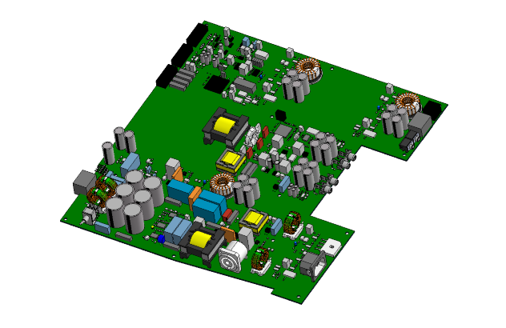
CircuitWorks for SOLIDWORKS® functions as the bridge between SOLIDWORKS and PCB design tools, offering bidirectional PCB design and revision.
CircuitWorks is an add-in available with SOLIDWORKS Design that helps bring PCB design into the SOLIDWORKS environment. It improves collaboration between ECAD and MCAD teams by allowing PCB layout information to be imported directly into SOLIDWORKS models. Users can also define assemblies in SOLIDWORKS and send them back to their preferred PCB design tool. This bidirectional workflow helps teams work more efficiently without disrupting their existing design process.
Use this solution to improve the way your team creates, documents, reviews, and prepares product designs. Khodiyar Infotech helps you choose the right SOLIDWORKS software, plan licensing, train users, and support adoption after implementation.

CircuitWorks for SOLIDWORKS augments your existing ECAD-MCAD workflow. Whether your circuit board design process starts with electrical components, mechanical components, or both concurrently, CircuitWorks’ two-way editing functionality seamlessly integrates within your product development workstream
Not only does CircuitWorks allow you to import PCB design files directly into SOLIDWORKS, but it also opens the door to the entire suite of SOLIDWORKS offerings. Run thermal analysis and other simulations on your PCB, preview your board directly within the CAD model of your product, and ultimately optimize your product designs for improved accuracy–all without the need for copious, costly physical prototypes.
CircuitWorks breaks down the barriers traditionally separating electrical and mechanical teams. Now, collaboration between the two teams occurs natively in the design file, thus streamlining the communication, revision, and collaboration processes between all stakeholders.
Let’s dive into the powerful communication and design tools united by CircuitWorks for SOLIDWORKS.
CircuitWorks supports bidirectional data exchange between SOLIDWORKS and your preferred PCB or ECAD tool, helping electrical and mechanical teams stay aligned. PCB files can be imported as SOLIDWORKS assemblies to check fit within the mechanical design, while design changes can be tracked and reviewed by both teams. It also supports updates such as board shape changes, hole locations, keep-ins, and keep-outs for better ECAD-MCAD collaboration.
Request Guidance →
CircuitWorks supports copper trace data from ECAD and PCB tools, allowing teams to bring accurate PCB details into SOLIDWORKS. Users can access mounting holes, copper geometry, traces, and vias while preserving important design rules, spacing, connectivity, and layer information. This helps create a more accurate PCB material stackup for mass, thermal, structural, shock, and electromagnetic analysis.
Request Guidance →
CircuitWorks helps teams manage PCB design files, revisions, markups, and edits in a more secure and organized way. Through its connection with the 3DEXPERIENCE platform or SOLIDWORKS PDM, design content can be centralized, stored safely, and shared more efficiently. This improves collaboration between teams while keeping important PCB design data controlled and accessible.
Request Guidance →
CircuitWorks connects PCB design with the wider SOLIDWORKS ecosystem, helping teams move beyond basic ECAD-MCAD collaboration. With SOLIDWORKS Flow Simulation, users can study thermal performance and identify heat buildup around PCB components before production. SOLIDWORKS Visualize can also be used to create professional, photo-quality renderings of PCB-equipped products. These integrations help teams improve analysis, presentation, and overall product development.
Request Guidance →
Use this section only when package comparison is relevant. Khodiyar Infotech can help you select the right license based on your workflow.
| Feature | Standard | Professional Recommended | Premium |
|---|---|---|---|
| 3D Part Modeling | ✓ | ✓ | ✓ |
| Assembly Design | ✓ | ✓ | ✓ |
| 2D Drawings | ✓ | ✓ | ✓ |
| Design Reuse Tools | ✓ | ✓ | ✓ |
| CAD Libraries | — | ✓ | ✓ |
| Manufacturability Checks | — | ✓ | ✓ |
| Cost Estimation | — | ✓ | ✓ |
| Photo-Realistic Rendering | — | ✓ | ✓ |
| Advanced Component Libraries | — | — | ✓ |
| Design Validation | — | — | ✓ |
| Motion Analysis | — | — | ✓ |
| Routing Tools | — | — | ✓ |
| Advanced Simulation | — | — | ✓ |
| Cloud Collaboration | — | ✓ | ✓ |
| Data Management Support | — | — | ✓ |
| Training and Support | ✓ | ✓ | ✓ |
Khodiyar Infotech can help you compare Standard, Professional, and Premium options based on your actual workflow.
Three ways to deploy SOLIDWORKS Design — pick the model that fits how your team actually works.
Ideal for individual designers, engineers, or professionals who need dedicated access.
Suitable for engineering teams, shared workstations, and controlled business environments.
For teams that need collaboration, review, and connected workflows across locations.
We do more than provide software. We help your team select, implement, learn, and use SOLIDWORKS with confidence.
Understand which SOLIDWORKS product and package fits your workflow.
Get clear guidance before investing in software.
Get assistance with setup, deployment, and onboarding.
Help your team build practical skills and use the software effectively.
Software value depends on how confidently your team can use it. We provide practical training to help users improve speed, accuracy, and workflow confidence.
Get up to speed on SOLIDWORKS fundamentals — modeling, sketching, drawings, and assemblies.
Tackle complex modeling techniques, surfacing, sheet metal, and weldments with expert guidance.
Train teams on shared workflows, design standards, libraries, and PDM best practices.
Model-based definition tools for communicating manufacturing information directly in 3D.
Combined electrical schematic and 3D electrical design capabilities.
Integrate electrical systems into 3D mechanical designs.
CircuitWorks for SOLIDWORKS is used by teams that need better coordination between PCB design and mechanical product design. It helps electrical and mechanical engineers exchange PCB layout data, review board fit, manage design changes, and validate electronic products inside the SOLIDWORKS environment.
Used when teams need to check how a printed circuit board fits inside a mechanical enclosure, housing, or product assembly before moving toward production.
Helps electrical and mechanical teams exchange PCB layout data, review changes, and keep both design environments aligned during product development.
Useful for products that combine circuit boards, connectors, housings, mounting points, thermal considerations, and mechanical packaging requirements.
Supports workflows where teams need to define or review board outlines, mounting holes, keep-in areas, keep-out zones, and component placement inside SOLIDWORKS.
Helps bring PCB geometry, copper traces, vias, and component details into SOLIDWORKS so teams can prepare more accurate data for thermal, structural, shock, and electromagnetic analysis.
Used when teams need to track PCB-related design changes, review revisions, and manage board updates between SOLIDWORKS and their preferred PCB design tools.
Find answers to common questions about CircuitWorks for SOLIDWORKS, including PCB data exchange, ECAD-MCAD collaboration, supported workflows, copper trace support, revision control, and how it improves electronic product design.
CircuitWorks for SOLIDWORKS is used to connect PCB design tools with SOLIDWORKS mechanical design workflows. It allows teams to import PCB layout data into SOLIDWORKS, review board fit inside the product model, and send mechanical design changes back to the PCB tool.
CircuitWorks helps electrical and mechanical teams work together by allowing PCB data to move between ECAD tools and SOLIDWORKS. This reduces communication gaps, helps both teams review design changes, and improves coordination during electronic product development.
Yes. CircuitWorks can import PCB design data into SOLIDWORKS so the board can be represented inside the mechanical assembly. This helps engineers check fit, clearance, mounting, and product packaging before physical prototyping.
CircuitWorks supports common neutral PCB exchange formats, including IDF, IDX/ProStep EDMD, and PADS ASCII files. These formats help teams exchange board data between SOLIDWORKS and PCB design tools.
Yes. CircuitWorks supports bidirectional design exchange, allowing changes to move between SOLIDWORKS and PCB tools. Teams can modify board shape, hole locations, keep-ins, and keep-outs while keeping electrical and mechanical teams aligned.
Yes. CircuitWorks can process copper trace data from ECAD or PCB tools into SOLIDWORKS. This helps create a more accurate PCB representation for mass, thermal, structural, shock, and electromagnetic analysis.
Yes. Once PCB data is available inside SOLIDWORKS, teams can use related SOLIDWORKS tools for analysis and visualization. For example, PCB-equipped products can be reviewed for thermal behavior or presented using realistic product visuals.
Yes. Khodiyar Infotech can help you understand CircuitWorks capabilities, evaluate your ECAD-MCAD workflow, guide you with licensing options, and support your team in using CircuitWorks more effectively with SOLIDWORKS.
Khodiyar Infotech can help you understand licensing, implementation requirements, training options, and the right next step for your team.